Learn all about Entity Relationship Diagrams (ERDs), what they are used for, how to understand them, how to create them, and more in this guide.
What is an Entity Relationship Diagram (ERD)?
An Entity Relationship Diagram (ERD) is a type of diagram that lets you see how different entities (e.g. people, customers, or other objects) relate to each other in an application or a database.
They are created when a new system is being designed so that the development team can understand how to structure the database. They can also be created on an existing system to help the team understand how the system works and to find and resolve any issues.
Entity Relationship Diagrams use a specific set of symbols, such as shapes and arrows, to depict the system and database.
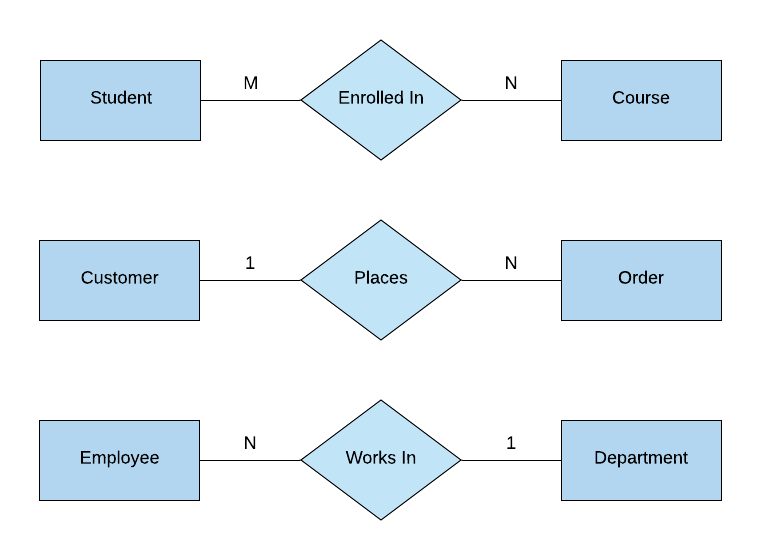
Here's an example of an ERD:

Components of an ERD
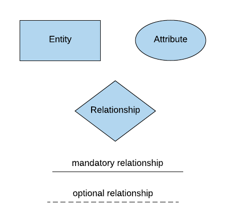
An Entity Relationship Diagram is made up of many different components:
- Entity
- Relationship
- Attribute
Entity
An entity is a thing that can have data stored about it. It can be a physical object (e.g. car, person), a concept (e.g. address) or an event (e.g. student enrolment in a course). They represent nouns.
They are usually represented as rectangles on an ERD with the entity name inside the rectangle.
An entity can also be a strong entity or a weak entity. What's the difference?
A strong entity has an identifier (a primary key) and does not depend on any other entities for it to exist. For example, a student may be a strong entity, as it can have a primary key and does not depend on any other entities for it to exist.
A weak entity is one that depends on a strong entity for existence. This means it has a foreign key to another entity. For example, an enrolment of a student may be a weak entity, as an enrolment cannot exist without a student.
Relationship
A relationship in an ERD defines how two entities are related to each other. They can be derived from verbs when speaking about a database or a set of entities.
Relationships in ERDs are represented as lines between two entities, and often have a label on the line to further describe the relationship (such as "enrols", "registers", "completes").
There are several types of relationships that are represented on an ERD:
- One to one: One record of an entity is directly related to another record of an entity
- One to many: One record of an entity is related to one or more records of another entity.
- Many to many: Many records of one entity can be related to many records of another entity.
Attribute
An attribute is a property of an entity or something that can be used to describe an entity. They are often represented as ovals, or as entries inside an entity.
There are several different types of attributes represented on an ERD:
- Simple: an attribute that cannot be split into other attributes, such as a first name.
- Composite: an attribute that can be split into other attributes, such as name being split into first, middle, and last name.
- Derived: an attribute that is calculated or determined from another attribute, such as the age of record being calculated from the created date.
An attribute can also be single-value or multi-value:
- Single-value: an attribute that is only captured once for
- Multi-Value: an attribute that can be captured more than once for an entity, such as multiple phone numbers.
What is Cardinality?
Cardinality represents the number of instances of an entity that exist in a relationship between two entities. This is often expressed as a number but could also be a symbol, depending on the style of diagram used. Common cardinality values are zero, one, or many.
We'll see some examples of cardinality later in this guide.
Natural Language
When we are creating an ERD we often have an idea of what we want to capture. This can usually be expressed in words, or using "natural language".
Some examples are:
- "Record students, courses they enrol in, and teachers who teach the course"
- "Capture the customer orders, customer details, and where the orders are being sent"
- "Capture patient data and the operations they had"
These sentences include a few different types of words, which can be used as a starting point for an ERD. They are represented in a few different ways:
- Noun: a "thing", such as a student or customer. Represented as an entity.
- Verb: an action, such as enrol or send. Represented as a relationship between two entities.
- Adjective: a describing word, such as residential or advanced. Represented as an attribute on an entity.
This can help you translate a description of what you need to diagram into an actual diagram.
Symbols and notations
When creating an ERD, it can be simple to create boxes and lines between them. But, like many things in software development, there are a few different methods and standards that are available. For ERDs, there are several notation standards, which define the symbols used.
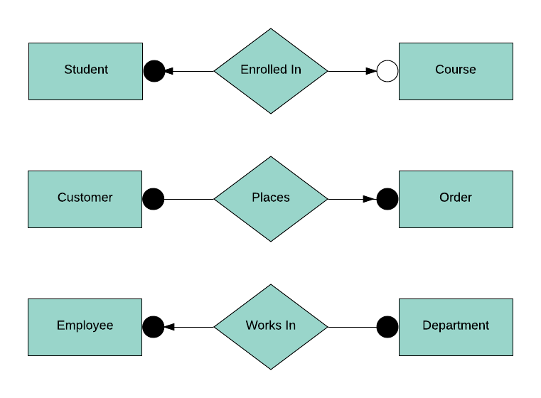
Chen
Here's an example of the symbols used with the Chen notation style.
Here's an example ERD using Chen notation:
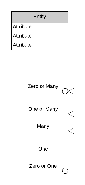
Crow's Foot
Here's an example of the symbols used with the Crow's foot notation style. This is the style you'll see the most on Database Star as it's the one I'm most familiar with. It's called "crow's foot' as the symbol for a many relationship looks like the foot of a crow with its three prongs.
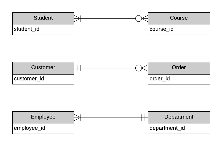
Here's an example ERD using Crow's Foot notation:
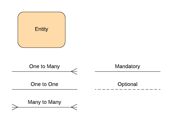
Bachman
Here's an example of the symbols used with the Bachman notation style.

Here's an example ERD using Bachman notation:
IDEF1X
Here's an example of the symbols used with the IDEF1X notation style.
Here's an example ERD using IDEF1X notation:
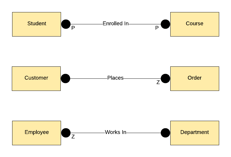
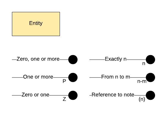
Barker
Here's an example of the symbols used with the Barker notation style.
Here's an example ERD using Bachman notation:

Conceptual, logical, physical
An Entity Relationship Diagram can be drawn at three different levels: conceptual, logical, or physical.
Each of these levels has a different level of detail and are used for a different purpose.
Let's see some examples.
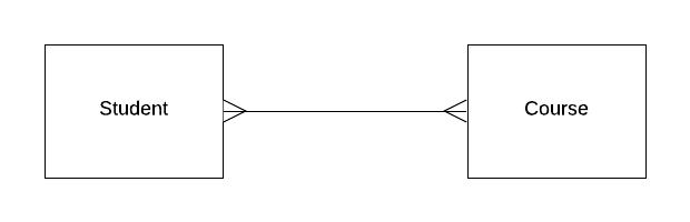
Conceptual Data Model
The conceptual data model shows the business objects that exist in the system and how they relate to each other.
It defines the entities that exist, which are not necessarily tables. Thinking of tables is too detailed for this type of data model.
An example of a conceptual data model is shown here. It shows students, courses, and how they relate.
Logical Data Model
A logical model is a more detailed version of a conceptual data model. Attributes are added to each entity, and further entities can be added that represent areas to capture data in the system.
Here's an example of the student and course data model created as a logical data model.
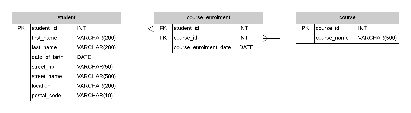
Physical Data Model
The physical data model is the most detailed data model in this process. It defines a set of tables and columns and how they relate to each other. It includes primary and foreign keys, as well as the data types for each column.
These diagrams can be created manually in a data modelling tool. They are also often generated by an IDE from an existing database.
Here's an example of the student and course physical data model.
This table outlines the differences between a conceptual, logical, and physical model:
| Feature | Conceptual | Logical | Physical |
| Entity | Yes | Yes | Yes |
| Relationship | Yes | Yes | Yes |
| Attribute | Yes | Yes | |
| Attribute Types | Yes | ||
| Keys | Yes |
How to Create an Entity Relationship Diagram
So how do you create a data model or an Entity Relationship Diagram?
I've detailed this in my Relational Database Design course, and I've also explained it in my guide to designing a database.
The process to create an ERD is:
- Write a sentence or two about what you are storing data about
- List what you're storing data about – the nouns/objects
- List the information you want to store for each object
- Describe the relationships between each object
- Draw the diagram
The steps listed here are brief but the process can take some time, depending on how familiar you are with the system and how experienced you are with creating Entity Relationship Diagrams.
Tools to Use
What tool should you use to create a data model or an Entity Relationship Diagram?
There are a lot of applications available to help you create one. I've written a post that lists them all with a comparison of major features and price, which you can find here: 79 Data Modeling Tools Compared.
Personally, I use LucidChart as it's simple to use and web-based. But in the past, I've used Visio and even the data modelling capabilities inside an IDE.
That page above includes a range of tools and some recommendations if you're not sure what to use.
You can also start with a pen and paper to get an understanding of how a diagram can be created. I often start by drawing one in my notebook. It gets messy eventually, but I transfer it to an electronic copy anyway.
Tips for Creating an Entity Relationship Diagram
Here are some tips for creating an Entity Relationship Diagram:
- Determine the right level of detail based on the purpose of the diagram. Development teams often find the logical model the most useful, but others might find the conceptual model more valuable.
- Review the entities and attributes to see if they include everything you want to store in the system.
- Name all entities and attributes.
- If you have a large diagram, consider using colours to highlight different sections, or breaking it up into smaller diagrams.
- Be consistent with your naming and the symbols you use.
Conclusion
An Entity Relationship Diagram is a great tool to help you define, understand, and communicate the requirements of a system. It can be modelled at a high level (conceptual data model), a detailed level (physical data model) or a level in between (logical data model).
There is a range of modelling notations or types of symbols which define how entities, attributes, and relationships are captured.
If you want to get started with creating an ERD for your system, consider drawing one on paper, or use one of the many tools available.
Source: https://www.databasestar.com/entity-relationship-diagram/
Posted by: schuchgonzalosays.blogspot.com

Posting Komentar